
The CAD to Factory Floor Gap: Why Your 3D Renders Are Unmanufacturable (And How to Fix Them)
Your 3D render looks great and your stakeholders are thrilled with the photorealistic visualisations. But has it been designed for manufacturing (DFM): the factory doesn't care how good your CAD model looks on screen. Every year, product creators lose months of development time and thousands of dollars when their "finished" designs stall at the modelling and tooling stage because nobody checked whether the product could be mass produced. This gap between CAD design and production is where unit costs explode unexpectedly. Only a holistic approach to product development can avoid this and other downstream cost blowouts. Understanding how to close that gap is the single most valuable engineering skill a product creator can develop. Unfortunately, if you are not using a designer with intricate knowledge of the entire product process, including shipping, there are bound to be mistakes in the render.
The Hidden Cost of the ‘Perfect’ 3D Render
Modern CAD software is extraordinarily powerful. It lets you model compound curves, razor-thin walls, and complex internal geometries with a few clicks. But that power creates a dangerous illusion: if the software lets you draw it, it must be buildable.
It isn't. Not always.
A polished 3D render tells you nothing about:
Flow rates and tool balancing - Whether hot plastic can actually flow into that geometry evenly
Undercuts - Whether the part will release cleanly from a mould after cooling
Production durability/material shrinkage - Whether your tolerance stack-ups will hold across a 50,000-unit production run or across different materials
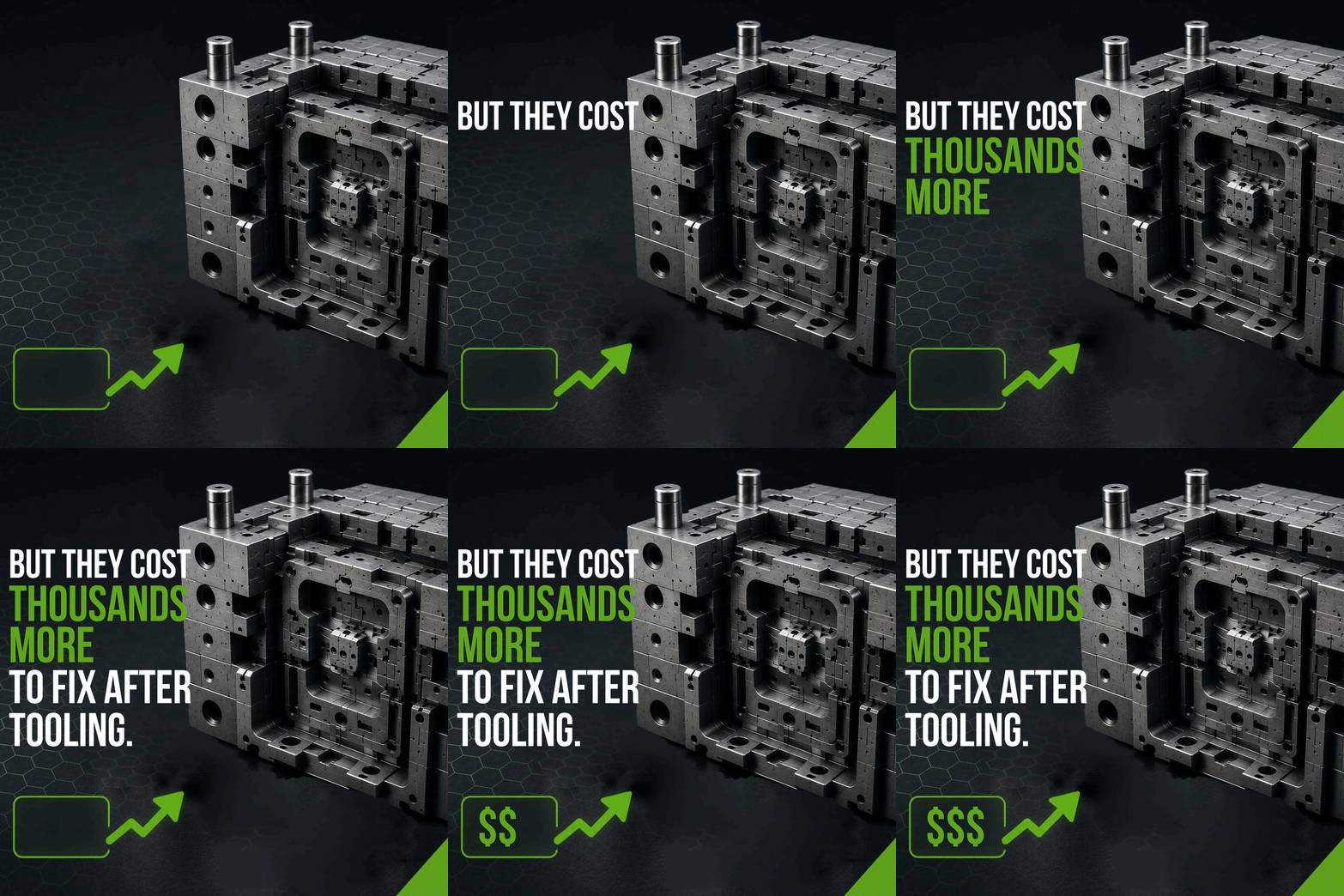
Whether the tooling required will cost $15,000 or $65,000
The render is a dream. Design for manufacturing renders are promises. Without a proper DFM review before tooling begins, product creators routinely discover that features which looked elegant in SolidWorks or Fusion 360 are mechanically impossible — or prohibitively expensive — to produce at scale.
Learn about Tincat's Design Optimisation services
Three DFM Oversights That Delay Tooling for Months
After decades of managing product development and production across the globe, we've seen the same three DFM mistakes stall projects over and over again. Each one seems minor in CAD but creates major consequences once tool steel is involved.
1. Missing Draft Angles and Joins
Most products, especially functional ones, are required to be assembled with working internal parts. Illustrators and concept designers often design an elegant product without understanding how it is going to be finally tooled and without enough room for the components. Draft angles are the slight tapers applied to vertical walls so a part can eject cleanly from a mould. Without adequate draft parts stick, scrape, and deform during ejection. Textured surfaces need even more. The result? Surface defects, mould damage, and costly tool rework before a single production unit ships. Understanding where the part lines will form on the finished product also needs to be taken into consideration. 3D renders typically don’t display joins, part lines or injection points that can ruin the outlook of a product if not managed well enough. For example, we recently saw a product that required retooling where a factory tooled off a 3D illustration and put the screws right where it was held. That was the only way to allow space for the internal parts, but it made it uncomfortable for the user and broke the streamlined aesthetic that the designer was going for.
2. Undercuts That Demand Complex Tooling
Undercuts are features that prevent a part from being pulled straight out of a mould. Hooks, internal clips, and snap-fit details are common culprits. Every undercut potentially requires additional slides, lifters, or collapsible cores in the mould — each adding $5,000–$20,000+ to tooling costs and weeks to lead time. In many cases, a small design adjustment can eliminate the undercut without sacrificing functionality. Holistic product developers take this into consideration at this early stage. Undercuts can also lead to a factory following the design faithfully and requiring multiple parts that need to be assembled after injection. We see this a lot with figurine concept drawings. The issues this creates is higher total cost of product and often a failure at the safety testing because of all the manually assembled parts not having consistent glue or simply not being strong enough. A quick DFM review allows some parts to be fused (without losing the overall character appeal) creating a safer, cheaper figurine.
3. Non-Uniform Wall Thickness or long thin parts
When wall thickness varies significantly across a part, different sections cool at different rates. The thicker sections shrink last, pulling the surface inward and creating visible sink marks, warpage, and internal voids. To avoid this some factories increase the pressure which creates ‘flashing’ (the very thin fins of plastic that extend from the join lines). For injection-moulded parts, best practice is to maintain wall thickness within ±10% variation and ensure transitions are gradual — not abrupt. Getting this wrong forces either a mould redesign or permanent cosmetic compromises. Understanding this early allows for workarounds that can be discussed with stakeholders at an early stage. Tincat will often present multiple options on how this could be handled.
These three issues alone account for the majority of tooling delays we encounter. Catching them before committing to tooling saves weeks and thousands of dollars.
Explore Tincat's Engineering, Tooling & Production capabilities
How to Bridge the Gap Between Industrial Design and Mechanical Engineering
The root cause of the CAD-to-factory-floor gap isn't bad design talent — it's a gap in holistic knowledge. And this, we at Tincat see again and again, is the biggest hidden cost in developing your own product.
Many domain specialists simply do not have experience in the entire process. For example; industrial designers optimise for aesthetics, ergonomics, and user experience while mechanical engineers optimise for stress loads, material behaviour, and assembly. But neither discipline, working alone, optimises for what the factory can actually produce efficiently or what the customer needs. The team at Tincat work in unison. Our product design team regularly spend time in the factory to ensure that they are familiar with production limitations and the most recent production developments.
Bridging this gap requires:
Early process selection — deciding whether a part will be injection moulded, CNC machined, die cast, or 3D printed before detailed CAD work begins. This allows a holistic designer the ability to design for manufacturing at the same time as meeting the client’s requirements.
Tolerance realism — applying tight tolerances only to features that genuinely require them (mating surfaces, bearing fits) and relaxing everything else to standard manufacturing capability. Also understanding that so much of manufacturing is still manual and designing the product to allow for a range (tolerance) of expertise in assembly.
Iterative DFM reviews — checking the design against manufacturing constraints at concept, detailed design, and pre-tooling stages, not as a one-time afterthought. And this is where Tincat shines. Our close-knit, experienced team follows robust design and development protocols to ensure that all stages of the product cycle are addressed at the concept stage.
The product creators who consistently ship on time and on budget are the ones who treat design for manufacturing as a parallel workflow — not a final checkbox.
Tincat's Approach: Pre-Production DFM Optimisation
At Tincat, we run on-the-ground DFM engineering reviews across our offices in Melbourne, China, Vietnam, and Hong Kong — before tool steel is ever cut, in fact, when we work with you on your ideas we do this at the very first sketch. This isn't a software-generated report. It's a hands-on assessment by highly experienced engineers, industrial designers and product developers who walk factory floors daily and understand what each facility and process can (and can't) deliver.
Our DFM optimisation process covers:
Draft analysis across every vertical surface, adjusted for material, texture depth, and mould configuration
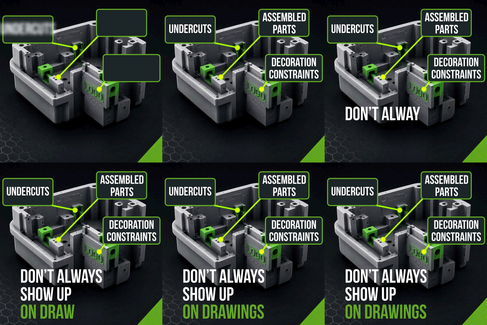
Undercut elimination or simplification, redesigning features to reduce slide and lifter requirements wherever possible
Assembly requirements to determine where robust joins are required or where parts could be redesigned to be made as one part, reducing cost and increasing durability.
Decoration review to ensure that once tooled there is adequate smoothness and angles to apply the painting, printing and other decoration onto the product
Tooling requirements and part selection to determine how many tools would be required, which parts could be grouped together and how to maximise dollars on tooling vs cost of product for the lowest total cost of goods.
The result is a design that has been pressure-tested against real factory capability — not just simulated. When your files reach the model- or tool-maker, they're ready. No surprises. No six-week delay while the mould is redesigned. No ballooning unit costs.
Ready to Close the Gap Between Your Design and the Factory Floor?
Tincat helps product creators worldwide move from concept to production without the costly surprises. Our on-the-ground teams in China, Vietnam, and Hong Kong review your designs against real factory capability — before a single dollar is spent on tooling.
✅ Get a pre-tooling DFM engineering review from engineers who work on factory floors daily
✅ Identify and resolve draft, undercut, tolerance, assembly, functionality and wall-thickness issues before they become expensive problems
✅ Contact Tincat today to discuss your project →
Frequently Asked Questions
-
A: Design for Manufacturing is the engineering practice of optimising a product's design so it can be produced efficiently, consistently, and cost-effectively using the intended manufacturing process. For product creators moving to injection moulding, die casting, or other high-volume methods, a proper DFM review identifies issues like missing draft angles, problematic undercuts, and inconsistent wall thickness before tooling — preventing costly rework, production delays, and inflated unit costs.
-
A: Ideally, DFM thinking should begin during the concept phase, when process and material decisions are first being made. A formal DFM review should be completed before any tooling investment. Changes at the CAD stage cost hours; changes after a mould is cut cost thousands of dollars and weeks of delay. Tincat recommends an iterative approach, with DFM checks at concept, detailed design, and pre-tooling stages.
-
A: Absolutely. Many of our clients come to us with finalised CAD files that need a manufacturing reality check. Our engineering teams review the design against the specific capabilities of the factories we work with, flag issues, and recommend targeted adjustments. This pre-tooling optimisation regularly saves clients significant time and money while preserving the design intent of the original product vision.
Your Digital Design Deserves a Manufacturing-Ready Future
The gap between a stunning 3D render and a production-ready product isn't a mystery — it's a solvable engineering challenge. By addressing draft angles, undercuts, and production tolerances early, and by working with a partner who understands what happens on the factory floor, you protect your timeline, your budget, and the quality of your finished product. At Tincat, we've spent decades helping inventors, designers, retailers, and businesses close the CAD-to-factory-floor gap and ship products that look as good in hand as they do on screen. If you're ready to move from render to reality, let's talk.
Written by the Tincat Team